
See the entire The Fantastic Machine series →
“The last mile is always the longest.”
—Unknown
Welcome back to your training. Up to this point you’ve seen where power is born in massive generation stations and mastered the transmission system, the great circulatory system of the grid.
Now, you’re about to learn about the network of neighborhood poles, wires, and transformers that takes power from a local substation and delivers it right to your customer’s doorstep. While the transmission system you learned about in Part 3 is a resilient, interconnected web, the distribution system is built more like a tree. It is incredibly efficient at spreading power out to millions of individual customers, but it is also more vulnerable. This is the “final mile,” and it is where the vast majority of your customer outage calls will originate. A squirrel, a fallen tree branch, or a car hitting a pole here can leave a whole neighborhood in the dark. Let’s follow the path of power as it makes this last critical step.
The Distribution Substation, Gateway to the Neighborhood
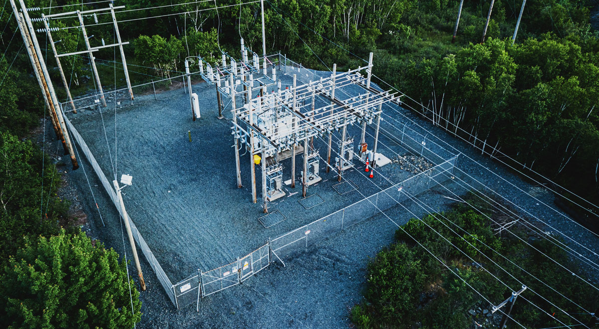
Your journey into the neighborhood begins when power exits your high-voltage transmission system and enters a distribution substation. Think of these as a scaled-down version of the massive transmission substations you studied in Part 3. While a transmission substation is a major hub for moving bulk power across the country, a distribution substation has a much more localized and specific purpose, to be the gateway to the community. They are physically smaller, with more compact equipment, because they handle lower voltages and far less power than their transmission-level counterparts.
Their primary job is to take electricity from transmission levels, like 138,000 volts, and perform the final major step-down to a medium-voltage level, typically between 4,000 and 35,000 volts. This is done by a large power transformer, whose role is more focused than in a transmission yard. It is not stepping up voltage from a generator or interconnecting two different high-voltage lines; its sole purpose is to prepare power for safe delivery to your customers. Beyond the transformer, a distribution substation contains a mix of shared and specialized equipment.
- Voltage Regulators: This is a key piece of equipment you will find here that is absent from a transmission substation. These devices, known as voltage regulators, are constantly at work, fine-tuning the voltage to keep it within a precise, acceptable range. As your customers’ demand fluctuates throughout the day, the voltage on the system can sag due to the principles of resistance you learned in Part 1. Regulators automatically adjust to boost it back up, ensuring the power you deliver is stable and consistent.
- Circuit Breakers and Reclosers: While transmission substations have massive circuit breakers, the protective devices here are built for a different philosophy. These large breakers and reclosers act as the main fuses for the entire neighborhood network. They monitor the power flowing out of the substation and are designed to automatically attempt to restore power after temporary faults, a common occurrence on the distribution system.
- Capacitor Banks: In Part 1, you learned about reactive power, the “foam in the beer.” While transmission systems use large capacitor banks for broad voltage support, here they serve a more tactical role. You will see racks of these capacitors used to produce reactive power locally, counteracting voltage drop on long feeders and improving the efficiency of power delivery to your customers.
- Control House and Grounding Grid: Some infrastructure is universal. Just like a transmission substation, a distribution sub has a control house that acts as the local brain, housing protective relays and communication gear. It also has a buried grounding grid connecting all metal components, which is a fundamental safety system regardless of voltage level.
Once the voltage is stepped down and regulated, the power is ready to be sent out into the neighborhood.
The Primary System, The Medium-Voltage Network
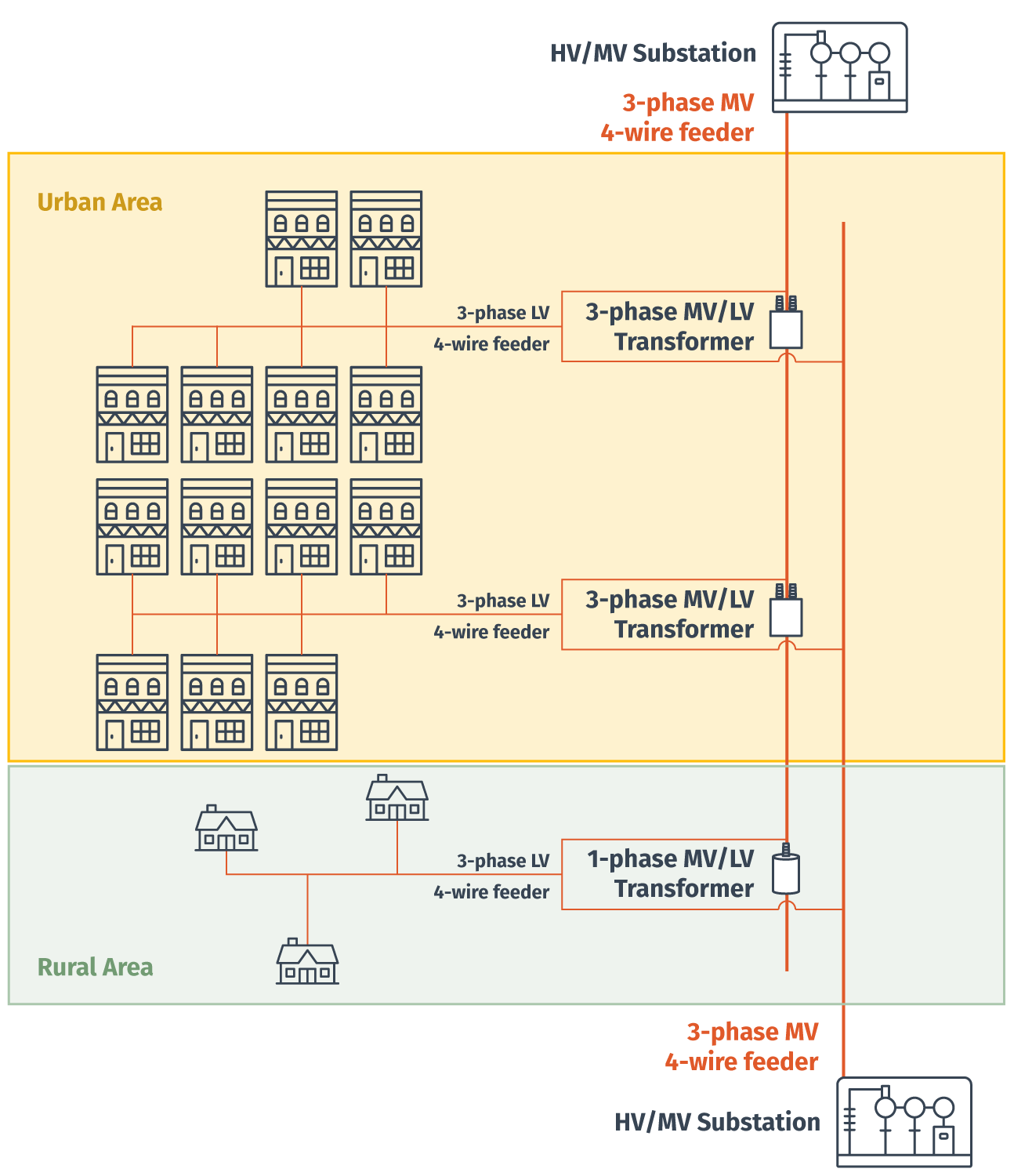
From the substation, power flows out onto the primary system. This is the medium-voltage network that forms the backbone of local delivery. This network is made up of several distinct circuits, and each complete circuit leaving the substation is called a feeder. Think of each feeder as a major artery leaving the heart.
Each feeder has a main backbone or mainline, which is the heavy, three-phase power line that carries the bulk of the power for that circuit. Branching off this mainline are smaller lines called laterals or taps. These are typically single-phase lines that peel off to serve individual streets or smaller groups of customers. Understanding this hierarchy of feeder, mainline, and lateral is critical for pinpointing the location of a fault.
Three-Phase vs. Single-Phase in the Field
This hierarchy connects directly back to what you learned in Part 1. The feeder mainline is three-phase for the same reason the transmission system is: it is a more efficient way to transport more power. It is also necessary to serve large commercial customers like grocery stores or industrial parks that have heavy machinery with three-phase motors. Residential homes, however, do not need this. Their loads are much smaller and can be served more economically by tapping off just one of the three phases. This is why you will see a three-phase mainline running down a major road, with single-phase laterals branching off to serve the residential streets.
That might raise a question for you. In Part 1, you learned that electricity needs a complete circuit to flow. So how can this system be a circuit if the power only seems to flow in one direction? The answer lies in a wire you often see running alongside the main power lines: the neutral wire. Each feeder is a complete circuit because it has at least two wires: a “hot” or phase wire that delivers power from the substation, and the neutral wire that acts as the return path. After the electricity does its work at a customer’s home, the current flows back along the neutral wire to the distribution transformer and ultimately back to the substation, completing the loop. So, while the network is “radial” in how it delivers power outwards, the underlying physics of a complete circuit is always maintained.
Network Configuration
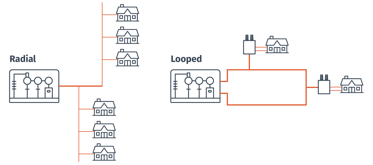
Most residential distribution systems you will manage are radial. This means power flows in one direction from the substation along a feeder’s mainline, which then splits into smaller laterals to serve individual streets. This design, which looks like the branches of a tree, is simple and cost-effective. Its main drawback, however, is a lack of redundancy. If a fault occurs on a branch, everyone “downstream” of that fault loses power until your crews can fix it.
In contrast, some critical commercial areas or dense urban centers may use a looped or networked configuration. In this design, the feeders are interconnected. This provides a redundant, two-way path for power to flow. If one section of the line is damaged, power can be automatically or manually rerouted from the other direction. This often restores power in seconds and dramatically increases reliability for places like hospitals and downtown business districts. This is a similar design philosophy to the highly “meshed” transmission network you learned about in Part 3, just on a much smaller scale.
Overhead vs. Underground
One of the most fundamental design choices you will see in the field is how these primary feeders are physically built. It is a decision that pits cost and practicality against aesthetics and resilience, and the choice made decades ago will directly impact the types of problems you manage today.
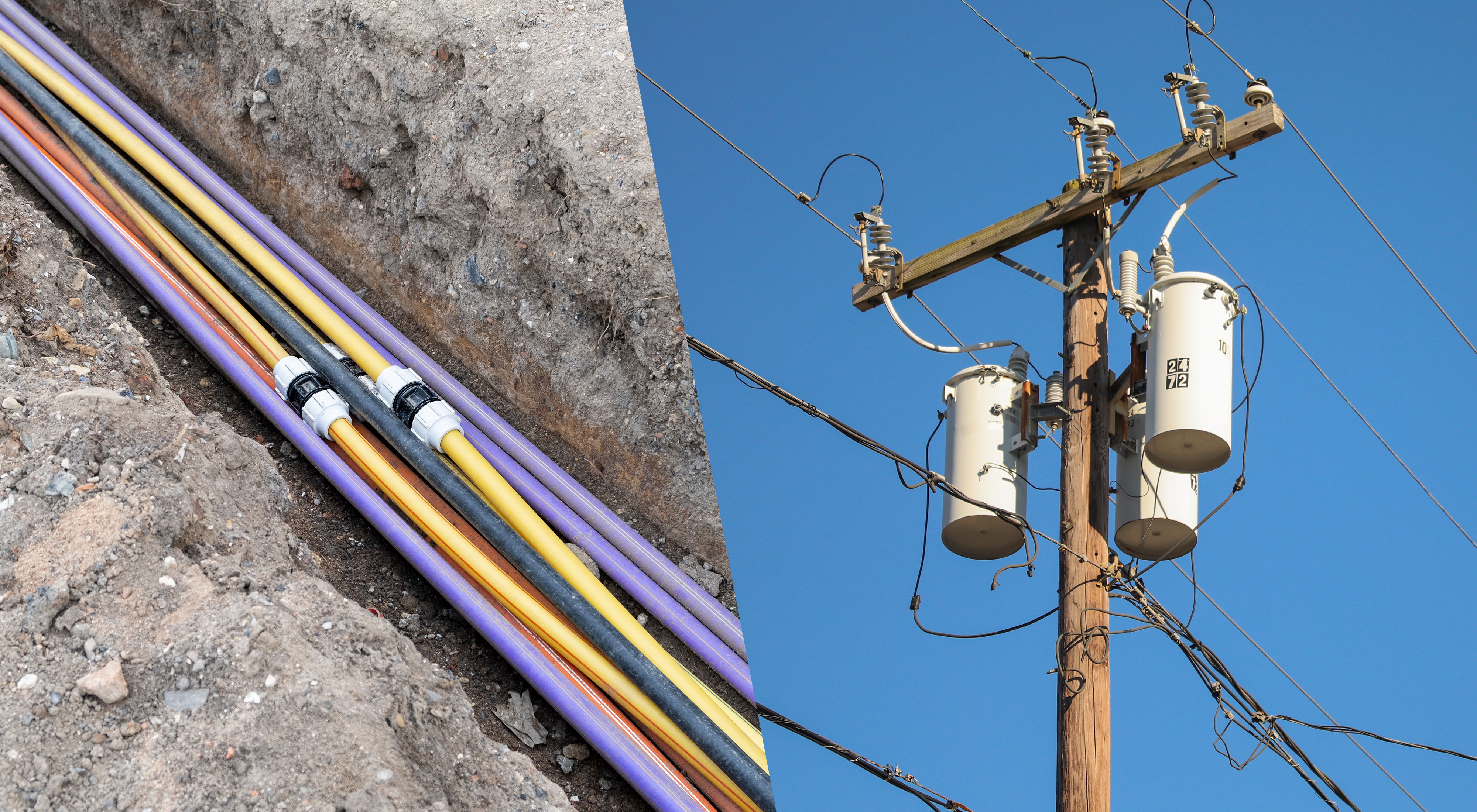
- Overhead lines are the familiar wooden utility poles and wires we see lining our streets. This method is far cheaper to build and makes it much easier for crews to find and repair damage. The trade-off is that the lines are exposed to weather, falling trees, animals, and vehicle accidents.
- Underground lines are buried in trenches. This approach, which makes the lines invisible and protects them from weather and accidents, has become the standard for many new residential neighborhoods and other developments. While this improves aesthetics and reliability, the trade-off is significant. Underground systems are much more expensive to install, and when a fault does occur in a buried cable, it can be very difficult and time-consuming for your crews to locate and repair.
Ultimately, there is no single right answer. The system you manage is a hybrid, a patchwork of older overhead areas and newer underground developments. Understanding this distinction is key, as it tells you a lot about the potential vulnerabilities of any given neighborhood before you even get the first outage call.
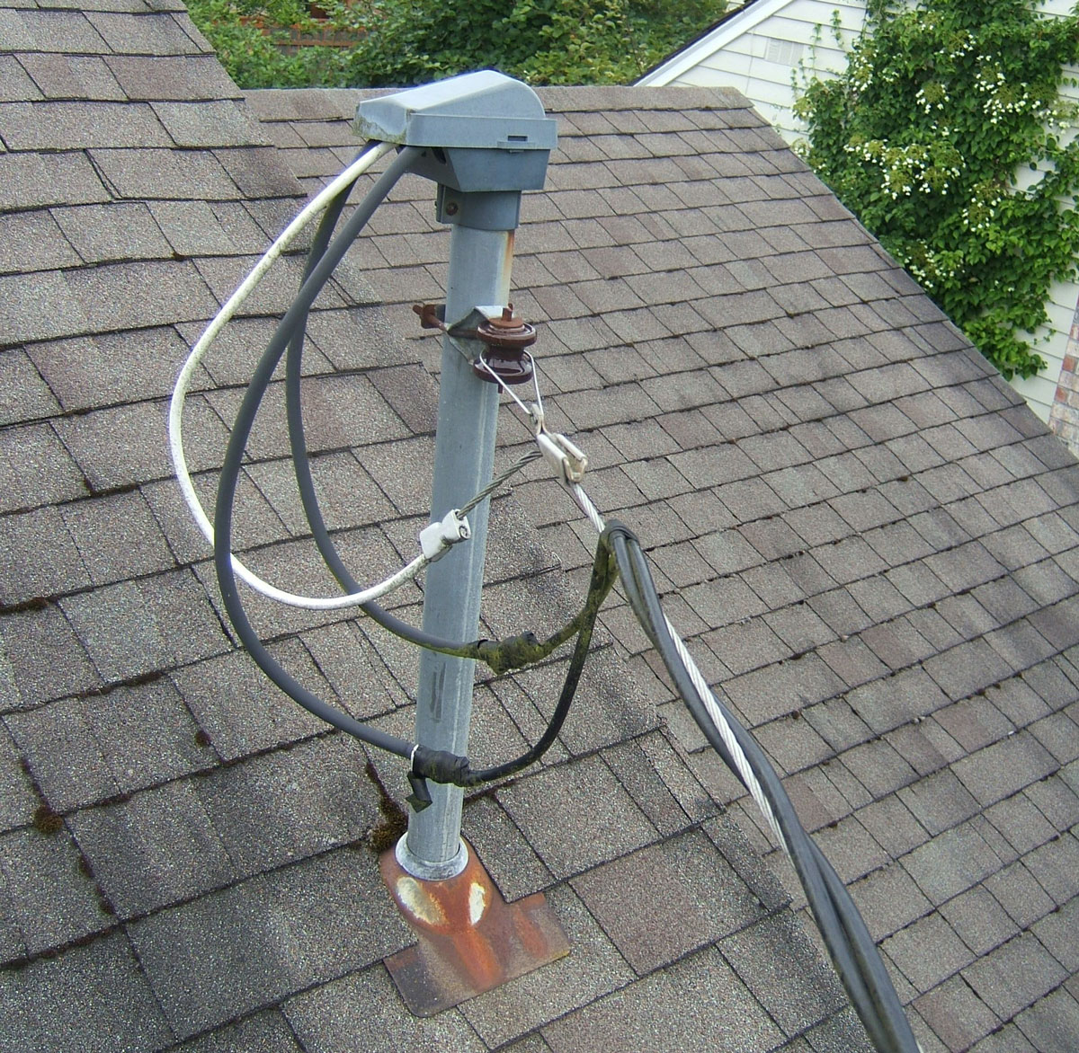
Anatomy of a Utility Pole
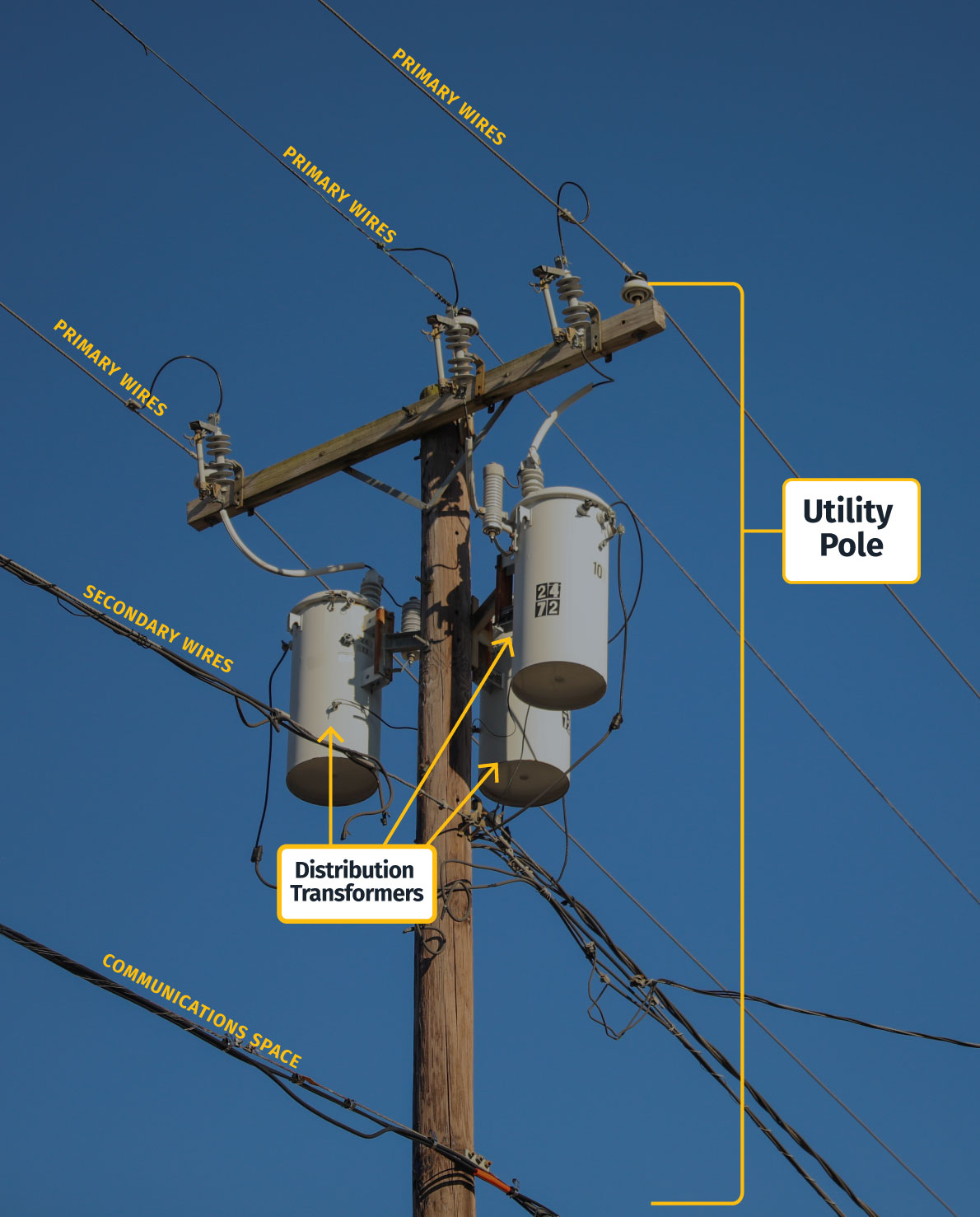
To connect these abstract concepts to the real world, you need to learn how to read the infrastructure in front of you. Every utility pole tells a story about how power is being delivered. Let’s break down what you are actually seeing on a typical neighborhood pole, from top to bottom, so you can understand the function of each component.
- The Primary Wires: At the very top, held on cross-arms by insulators, are the medium-voltage primary wires. They are placed at the highest point for safety, keeping them clear of traffic and trees. These wires carry the electrical “pressure” needed to push power throughout the neighborhood, typically between 4,000 and 35,000 volts. If you see three wires, it is a three-phase mainline serving a large area. If you see only one, it is a single-phase lateral tapping off that mainline to serve a specific street.
- The Distribution Transformer: That familiar grey can is the transformer, the workhorse of the secondary system. It takes the high pressure from the primary wire and, using the principle of magnetic induction you learned about in Part 1, steps the voltage down to the 120/240V level that is safe for use in homes. You will see a thin wire connecting it to the primary line above, and thicker, bundled wires coming out the bottom.
- The Secondary Wires: The thick, often bundled wires below the transformer are the low-voltage secondary lines. These carry the 120/240V power from the transformer and run from pole to pole, serving multiple houses from a single transformer. They are thicker than the primary wires because at the lower voltage, a higher current is needed to deliver the same amount of power, a direct application of the P = V x I formula from your first lesson.
- The Communications Space: The lowest set of wires on the pole does not belong to the power utility. This space is rented out to telephone, cable TV, and fiber optic internet providers. They are kept at the bottom, well away from the high voltage, for the safety of their line workers.
Seeing all this exposed equipment hanging on a pole makes it clear just how vulnerable the distribution system is. A single car accident or a falling tree branch can easily damage these critical components. This vulnerability is why the system is not just built to deliver power, but also to protect itself.
On-Line Protective Devices
Because the radial distribution system is so vulnerable, it relies on an automated immune system to keep small problems from becoming large ones. While the massive spinning generators you learned about in Part 2 provide system-wide inertia to handle supply and demand imbalances, these local devices are the physical first responders that deal with immediate threats like a fallen tree branch. The primary system is dotted with a family of protective devices designed to automatically detect and isolate faults, often before a customer even knows there is an issue. These are your first responders.
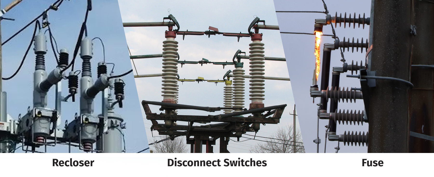
- Fuses: These are the simplest form of protection. You will see them on the cross-arms of utility poles. A distribution fuse is a simple wire designed to melt and break the circuit if the current gets too high. It is a one-shot device. Once it “blows,” it must be manually replaced by a line crew. Fuses are essential for protecting pole-top transformers from being damaged by a fault in a home or business. They also prevent a small problem from causing an entire feeder to go out.
- Reclosers: These are essentially “smarter” circuit breakers installed out on the lines. Many faults on the power grid are temporary, for instance, a tree branch brushing against a line or a lightning strike causing a momentary arc. A recloser will automatically trip the line open to clear the fault, then try to “reclose” a second or two later to restore power. It might do this two or three times. If the fault is still present, the recloser will lock open. This keeps the line de-energized for safety until a crew can fix it. This smart automation prevents countless momentary issues from turning into prolonged outages.
- Sectionalizers: Think of a sectionalizer as a smart teammate to an upstream recloser. It does not have the ability to interrupt a fault current itself. Instead, its job is to count the operations of the recloser. After a preset number of recloser trips, the sectionalizer determines the fault is permanent. The next time the recloser opens the circuit, the sectionalizer also opens, physically isolating the faulted section of the line. This allows the recloser to successfully restore power to the healthy parts of the feeder, dramatically improving reliability.
- Disconnect Switches: You will also see manually operated disconnect switches on the poles. Their sole purpose is to provide a clear, visible air gap in the line so that crews can safely work on a de-energized section of the circuit. It is critical to remember that these are not designed to interrupt current. They are only ever operated after a breaker or recloser has already opened the circuit.
Operator Briefing: The Humble Fuse
You might think of the fuse as a simple, low-tech device, but it was a revolutionary invention. Before Thomas Edison patented a workable fuse in 1890, “protecting” a circuit was a dangerously crude affair. Early systems used weaker sections of wire that were supposed to burn out first, but they were unreliable and often started fires. Edison’s design, a simple strip of metal in a fireproof casing, was the first device that could safely and reliably isolate a fault. Every fuse you see on a pole today, and even the ones in your car, are direct descendants of that simple, brilliant idea. It was one of the key inventions that made the widespread, safe distribution of electricity possible.
Having this family of devices is only half the battle. For the system to work, they cannot act independently. They must operate in a perfectly timed sequence, like a well-drilled team. This brings us to the hidden logic that governs your entire protection system.
The Art of Protection Coordination
You’ve learned about the basic protective devices like fuses and reclosers. Now you need to understand the art of making them work together. This is called protection coordination, and it is a core discipline of a protection engineer. It is a complex puzzle that ensures that for any given fault, the smallest possible section of the grid is taken offline.
Think of it as a chain of command. You want the device closest to the fault to operate first. You would never want a main circuit breaker at the substation, which serves thousands of customers, to trip for a fault caused by a single faulty transformer down the line. That transformer’s individual fuse should blow first, isolating the problem without affecting anyone else.
To achieve this, your engineering teams use sophisticated software to run short circuit analysis. They model what would happen if a fault occurred at every single point on the circuit. This analysis tells them the exact amount of fault current that would flow, which allows them to carefully select the size and operating time of every fuse, recloser, and breaker. The goal is to create a precise sequence where each device gives the one downstream of it a chance to clear the fault before it acts. Mastering this invisible logic is what separates a chaotic grid from a reliable one. But even the most perfectly coordinated system is still vulnerable to physical threats, the most common of which is the constant encroachment of nature.
This brings us to one of the most significant and unending operational challenges you will face. Keeping the lights on isn’t just about managing the flow of electrons; it’s also about managing the world around the wires.
The Constant Battle of Vegetation Management
Operator Briefing: The Great Blackout of 1965
Why is tree trimming such a non-negotiable part of your job? You can thank the Great Northeast Blackout of 1965. On a November evening, a single, improperly set protective relay on a transmission line in Ontario, Canada, tripped. The cascading power surge that followed knocked out power to over 30 million people across the Northeastern United States and Canada. The investigation that followed found that a major contributing factor was that power lines were sagging too close to trees. That single event fundamentally changed the industry. It led to the creation of the North American Electric Reliability Corporation (NERC) and established the mandatory, rigorous vegetation management standards that your crews follow to this day. It was a hard-learned lesson that a single tree branch can, in the right circumstances, take down a nation.
The single biggest cause of outages on your distribution system is not equipment failure. It is trees. Vegetation management is the relentless, year-round effort to keep tree branches from growing into or falling onto your power lines. It is one of the largest maintenance expenses for any utility.
Crews work on a cycle, trimming trees along every single mile of the distribution system every few years. This is a complex task that involves balancing the need for reliability with public concerns and local ordinances. A single overgrown tree can cause a momentary outage in a storm or a major, prolonged outage if it brings down a line. As an operator, you will be acutely aware of which circuits are most prone to tree-related issues, especially when a storm is on the horizon. While managing trees is crucial for reliability, it’s also a fundamental part of a utility’s most important responsibility: protecting the public from harm.
Your Highest Priority is Public Safety
Electricity is an incredibly powerful and useful force, but it is also inherently dangerous. The single most important part of your job is to ensure the safety of the public and your crews. The entire system is designed with multiple layers of safety to mitigate hazards.
- Shock Hazards and Downed Lines: The greatest risk is a downed power line. Remember the extreme voltages we discussed on the transmission system in Part 3? Even the ‘lower’ medium-voltage on these neighborhood lines is more than enough to be instantly lethal. You must treat every downed line as if it is live. Your first action during an outage report involving a downed wire is to ensure the line is de-energized and to coordinate with first responders to secure the area.
- Stray Voltage: Sometimes, due to faulty wiring or equipment, metal surfaces that should not be energized, like a manhole cover or a streetlight pole, can become electrified. This is called stray voltage, and it can be a serious hazard. Utilities have dedicated programs to regularly test for and correct these conditions.
Through careful engineering, robust construction standards, and rigorous operational procedures, we have made the delivery of electricity incredibly safe. But you can never become complacent. Every decision you make must have public safety as its primary consideration.
The Secondary System
All of these safety measures and protective systems are in place to manage the primary network. Now, let’s follow the power as it takes its very last, and safest, step into the secondary system that directly serves the customer. This is the very last step in the journey where the medium-voltage power is transformed one final time into the standard, usable voltage that powers our daily lives. All the complexity of generation and transmission comes down to this final, critical handoff.
Distribution Transformers
![]()
The workhorse of this final stage is the distribution transformer. In areas with overhead lines, this is the grey can you see mounted on a utility pole. However, in neighborhoods with underground utilities, you will see a different type: the pad-mount transformer. This is the green metal box that sits on a concrete slab in a customer’s yard or a common area.
Operator Briefing: The Green Box and the Suburbs
The pole-top transformer is the classic icon of the grid, but its green, boxy cousin, the pad-mount transformer, has a fascinating history of its own. Its development and widespread adoption are directly tied to the explosion of American suburbs in the 1950s and 60s. As new, sprawling neighborhoods were built, there was a huge public demand for a cleaner aesthetic without a sky full of wires. The pad-mount transformer was the key piece of technology that made large-scale, cost-effective underground residential distribution possible. Every time you see one of those green boxes, you are looking at a direct link to the post-war suburban boom that reshaped the American landscape.
Though they look different, their function is identical. They take the medium voltage from the primary line and step it down to the standard 120/240V used in homes. In an underground system, a primary lateral will “dip” down a pole on a nearby main road, transitioning from an overhead line to a buried cable. This cable then runs from one pad-mount transformer to the next, forming a loop through the neighborhood and serving a small group of homes from each box.
The Sizing Puzzle of Transformer Loading
Selecting the right size transformer for a given location is a critical engineering task. The size, rated in kilovolt-amperes (kVA), which is the unit for Apparent Power you learned about in Part 1, must be large enough to handle the peak demand of the homes it serves. If a transformer is too small, it can become overloaded, especially during a heatwave when everyone’s air conditioning is running. An overloaded transformer will not only provide low voltage to customers, but it can also overheat and fail, causing a localized outage. As neighborhoods evolve and customers add high-power loads like electric vehicles, your planning engineers must constantly re-evaluate transformer loading to stay ahead of the demand curve, a challenge similar to the load-following task you learned about in Part 2.
Split-Phase Service
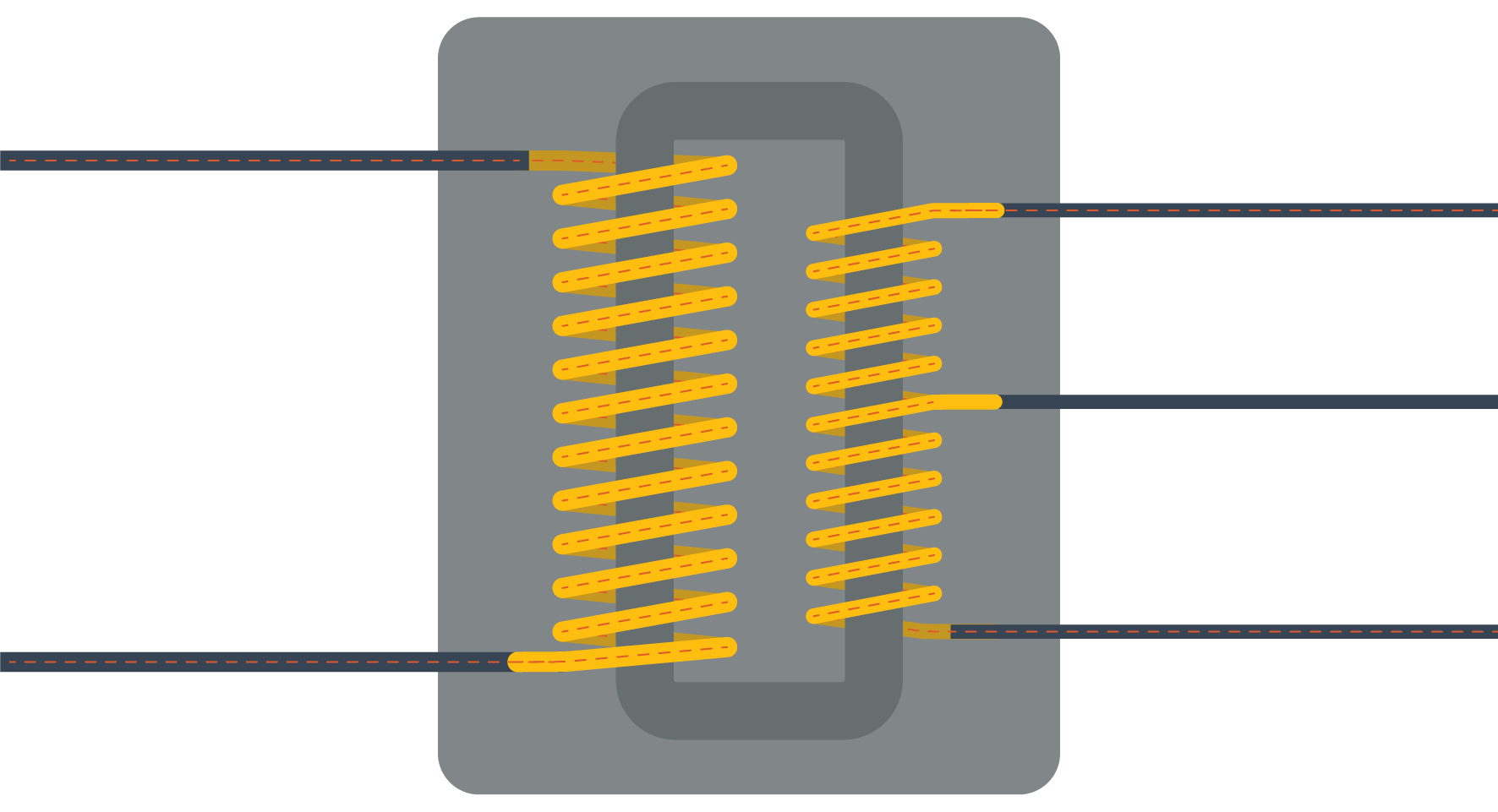
In North America, this final transformer provides what is known as 120/240V split-phase service. This clever design is the standard for nearly all residential customers. The transformer’s secondary coil has a center tap that is grounded, creating the neutral wire. The two ends of the coil become two separate “hot” legs. Because these two legs are at opposite ends of the coil, their sine waves are 180 degrees out of phase with each other. This configuration provides two distinct voltage levels from just three wires:
- Two 120V circuits for all their standard outlets and lights. This is achieved by creating a circuit between one of the hot legs and the neutral wire.
- One 240V circuit for high-power appliances like their air conditioner, electric stove, clothes dryer, or electric vehicle charger. This is achieved by creating a circuit between the two hot legs, giving access to the full voltage of the transformer’s coil.
This elegant and efficient design is the foundation of residential power delivery. But just providing these voltages is not enough; they must be delivered within a very specific and reliable range.
Service Voltage Standards
The voltage you deliver is not arbitrary. It is governed by a national standard, ANSI C84.1. This standard defines the acceptable voltage ranges that utilities must maintain. For a standard 120V service, “Range A” allows the voltage to be between 114V and 126V. This is the normal operating range.
Operator Briefing: Why 120 Volts?
Have you ever wondered why the standard voltage in North America is 120V, while it’s 230V in Europe and other parts of the world? The answer goes back to the very beginning. Thomas Edison’s first successful incandescent light bulb was designed to run on 110V DC. When AC systems were developed, they needed to be compatible with the existing light bulbs and appliances, so they adopted a similar voltage. Why did Europe go a different route? In the early 20th century, European utilities, particularly in Germany, made a calculated engineering trade-off. By doubling the voltage to 220V, they could deliver the same amount of power with half the current. As you know from Ohm’s Law, this meant they could use much smaller, cheaper copper wires, which was a huge advantage during periods of material shortages. The trade-off was a slightly higher risk of severe electric shock, but the economic benefits were too great to ignore. This decision, made over a century ago, is why you still need a converter when you travel abroad today.
The last mile of the distribution system is incredibly sensitive to load changes. As more customers on a circuit use more power, the voltage naturally drops. Your job, with the help of devices like voltage regulators and capacitor banks, is to ensure that even the customer at the very end of the longest line still receives voltage within that acceptable ANSI range. This is a constant balancing act.
The Service Drop
The final link in the chain is the service drop. This is the official point of demarcation where the utility’s responsibility ends and the customer’s begins. For overhead systems, these last few wires run from the transformer to the customer’s house, connecting at a point called the weatherhead, a protective, downward-facing conduit. However, in modern developments with underground utilities, the service drop is a buried cable that runs directly from a pad-mount transformer to the customer’s meter base, with no weatherhead needed. From the electric meter, which measures a customer’s energy consumption, the power flows into the customer’s main breaker panel. This panel is the customer’s own internal distribution hub, from which they control all the individual circuits in their home.
For over a century, this one-way path from the service drop to the breaker panel was the end of the story. Power flowed in, and that was it. But that entire paradigm is now being turned on its head, presenting you with one of the most significant operational shifts in the history of the grid.
The New Era of the Active Grid
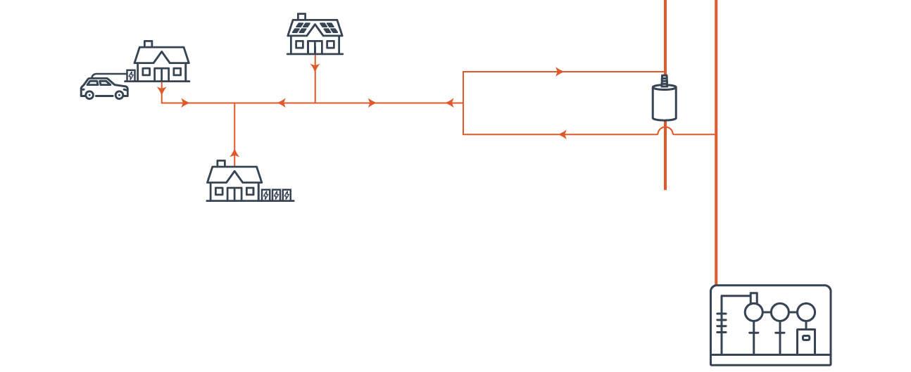
For a century, the physics of your job was straightforward. Power flowed one way, from the substation out to the customer. That era is over. Your customers are now active participants in the grid, installing their own Distributed Energy Resources (DERs) like rooftop solar, home batteries, and electric vehicles.
This creates a two-way flow of energy that fundamentally changes your job. Power is no longer just flowing “downstream” from you to the customer; on a sunny afternoon, it is also flowing “upstream” from thousands of solar panels back onto your grid. This reverse flow can cause complex problems, like dangerously high voltage, and can overload local transformers and wires that were never designed for it. This transforms the distribution grid from a simple delivery network into an active system, presenting operational puzzles similar to managing the non-dispatchable generation you learned about in Part 2.
To manage this new reality, you will rely on an expanding toolkit of technologies:
- Home Batteries: These systems are becoming a critical tool. They allow customers to store their excess solar energy for use at night, but their real value to you is in demand response programs. During a system peak, you can send a signal to a fleet of home batteries, asking them to discharge and serve their home’s load, or even export power back to the grid. This reduces stress on the system and can prevent you from having to fire up an expensive peaking power plant.
- Vehicle-to-Grid (V2G): An electric vehicle is essentially a large battery on wheels. Emerging Vehicle-to-Grid (V2G) technology allows a parked and plugged-in EV to not only charge from the grid but also to push power back into it. A fleet of V2G-enabled vehicles can act as a massive, distributed power source, helping you stabilize the grid during peak hours.
- Virtual Power Plants (VPPs): As we briefly touched on in Part 2, a Virtual Power Plant is the software that brings all of this together. A VPP is a cloud-based platform that can aggregate and control thousands of individual DERs, like home batteries and V2G vehicles. From your control room, you can dispatch the VPP just like a traditional power plant, asking it to provide a specific amount of power or load reduction. It is a powerful new tool for managing an increasingly complex and decentralized grid.
Hardening the Final Mile
The increasing frequency of severe weather and the threat of wildfires mean that simply restoring power after it goes out is no longer enough. For you as an operator, this is becoming a much bigger deal, as the time it takes to bring a customer’s power back on is being scrutinized more closely than ever before by both the public and regulators. Your performance is now measured by two key metrics:
- SAIDI (System Average Interruption Duration Index): This tells you, on average, how many minutes a customer was without power over the course of a year. You can learn more about SAIDI here.
- SAIFI (System Average Interruption Frequency Index): This tells you, on average, how many times a customer was interrupted during the year. You can learn more about SAIFI here.
A major part of your job will be focused on grid resilience, which means making the distribution system stronger to improve these numbers. This involves a range of strategies, from strategic undergrounding of power lines and more aggressive vegetation management to installing stronger poles. You will also manage microgrids, which are small-scale grids that can disconnect from the main system during an outage. By using local generation like solar and batteries, a microgrid can keep critical facilities like hospitals or fire stations running independently, providing a vital lifeline during a widespread emergency and dramatically improving the reliability scores for those customers.
Conclusion
And with that, your field tour is complete. You have followed the entire journey of power on its final mile, from the moment it leaves the substation, down the primary feeders that act as neighborhood arteries, through the final pole-top or pad-mount transformer, and across the service drop to the customer’s wall outlet.
You have seen that the distribution system is far more than just poles and wires. It is a complex ecosystem where the theoretical concepts from your earlier training become tangible realities. You now understand that its radial design, while efficient, creates unique vulnerabilities that must be managed through the precise art of protection coordination and the relentless, constant battle of vegetation management. You have learned that your job is not just about keeping the lights on, but about maintaining voltage within the strict limits of ANSI standards and ensuring public safety is always the highest priority.
This final mile is no longer a one-way street. The rise of customer-owned generation is transforming it into a dynamic, two-way network, presenting challenges in transformer loading and grid stability that your predecessors never faced. Hardening this system against modern threats and integrating this new wave of distributed energy will be the defining challenges of your career. It is a network that requires constant maintenance, careful engineering, and innovative thinking to deliver the seamless power everyone depends on.
Now that you’ve covered how power is made, moved, and delivered, your next training sessions will zoom back out. We will explore the complex world of the markets and organizations that control this immense machine, the sophisticated engineering tools you will use to keep it all in balance, and the incredible challenges and opportunities facing the grid as we transition to a cleaner, more electrified future.
See the entire The Fantastic Machine series →
Loved the article? Hated it? Didn’t even read it?
We’d love to hear from you.