

See the entire The Fantastic Machine series →
“The whole is greater than the sum of its parts.”
—Aristotle
Alright, welcome back to the control room. In your last training module, you saw where the power is born in massive generation stations and solar farms. But that power is useless until you can get it to the cities and towns that need it, often hundreds of miles away. Your next lesson is about how you move it.
Your domain is the transmission system. Think of it as the body’s circulatory system for electricity. It’s a network of high-voltage power lines and substations that forms the backbone of the grid, moving immense quantities of power across vast distances. This network is the core of what regulators call the Bulk Electric System (BES), which includes all the critical assets operating at 100,000 volts (100 kV) or higher. Let’s look at why the “pressure” in these arteries is so incredibly high.
![]()
Your Primary Tool: High Voltage
Look at the system map on the main screen. See those major lines crisscrossing the country? They operate at extremely high voltages, and for good reason. Your job isn’t just to move power, it’s to move it efficiently.
When electricity flows through any wire, you lose some of your product as heat. This is due to the wire’s electrical resistance. Over hundreds of miles, this loss could waste a huge portion of the power you’re trying to deliver. The physics behind this is governed by a simple but powerful formula you must never forget: Pₗₒₛₛ = I²R.
This means the Power Lost is equal to the Current (I) squared, multiplied by the Resistance (R) of the wire. That squared term is everything. If you can cut the current in half, you don’t just cut your losses in half. You reduce them by a factor of four! This principle is fundamental to the entire transmission system.

Recall from Part 1 that Power = Voltage × Current (P = V x I). This gives you an incredible lever to pull. By using massive transformers to “step up” the voltage to extreme levels like 230,000 volts, 500,000 volts, or even 765,000 volts, you can transmit the exact same amount of power with a much lower current. This massively reduces your losses and makes it possible to send power from a remote hydroelectric dam to a city on the coast. While the jump from 500 kV to 765 kV might not sound like a huge leap, it represents roughly a 2.5 times (I²!) increase in the amount of power a single line can carry.
These massive voltages dictate the design and scale of every part of the network. To make this system work, you have to rely on a collection of massive and highly specialized equipment.
The Blueprint of Your Network
Before we tour the equipment, it’s crucial you understand the fundamental design philosophy that makes your job possible. At a high level, the BES is designed as a highly networked or “meshed” system. This means there are multiple, parallel paths for power to flow between any two points on your grid. This architecture is the foundation of its reliability and is built to withstand the loss of a key element, a standard known as the “N-1” criterion. If you lose a major transmission line, power automatically and instantly reroutes over the remaining paths. Most of the time, your customers will never even know anything happened.
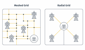
This stands in stark contrast to the radial architecture of the local distribution system, which we’ll cover in your next training. Those systems are built like trees, with a single path to each home. If a branch breaks, the lights go out. A problem on your transmission system is an operational challenge for you to manage. A problem on the distribution system is what usually causes a local power outage. While this meshed design provides reliability within a region, it’s crucial to understand that the entire continent is not one single, unified grid.
The Three Grids of North America: A Divided Nation
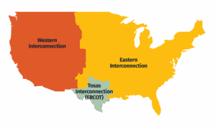
Now, here is a crucial detail. While we talk about the “North American grid,” it’s not one single, unified machine. It’s actually three massive, independent grids operating side-by-side, known as interconnections.
- The Eastern Interconnection covers the eastern two-thirds of the United States and Canada.
- The Western Interconnection covers the western third.
- The Texas Interconnection (ERCOT) covers most of Texas.
Within each of these massive regions, every generator is perfectly synchronized, spinning in lockstep to maintain a stable 60 Hz frequency. However, the three interconnects are asynchronous, meaning they are not synchronized with each other. At any given moment, the phase angle of the Eastern grid is slightly different from the Western grid. You cannot simply build an AC transmission line to connect them; doing so would be like trying to mesh two massive gears that are spinning at slightly different speeds. The resulting forces would be catastrophic.
Operator Briefing: The Great Divide
You might be wondering why the grid was built this way. The answer is a mix of history, physics, and politics. These grids grew organically from smaller, regional systems. By the time they expanded to cover vast areas, the engineering challenge of keeping a generator in Florida perfectly synchronized with one in Montana was immense with 20th-century technology. A single disturbance could have triggered continent-spanning blackouts.
This wasn’t just a theoretical problem. During the 1960s and into the mid-1970s, engineers maintained a handful of weak AC ties that connected the East and West. Keeping the two massive systems in sync through these tenuous links was a constant struggle. Massive, slow-moving waves of power would oscillate between the grids, threatening to pull both of them apart. Operators often had to preemptively open the ties to prevent a small disturbance on one side from cascading into a major problem on the other. Ultimately, this period proved that a coast-to-coast synchronous AC grid was simply too unwieldy to control with the technology of the day. While we could probably make it work now with modern control systems, the historical decision was made to abandon the AC ties and operate the systems independently.
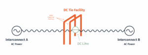
Your coordination with the operators in the other interconnects is limited and deliberate. It happens almost exclusively through a small number of special facilities called DC ties. These are essentially small, back-to-back HVDC converter stations that act as controllable energy gateways. They take AC power from one interconnect, convert it to DC, and then instantly convert it back to AC at the exact frequency and phase angle of the other interconnect. Think of them less like open highways and more like international border crossings for electricity where power transfers are scheduled transactions, not the free-flowing exchange you see within your own system.
However, the concept of a truly national grid is re-emerging. The limitations of this balkanized system are becoming more apparent as you need to move massive amounts of renewable energy across the country. This has given rise to ambitious proposals for a Macrogrid. The vision is to build a new overlay of high-voltage direct current (HVDC) lines that would act as an electrical superhighway, stitching the seams of the three interconnects together. This network would allow you to move solar power from the deserts of Arizona to the cities of the East Coast at night, or send wind power from the Great Plains to the West Coast during a calm spell. It’s one of the biggest and most exciting engineering challenges of the 21st century, and it could fundamentally change the map on your screen. But before we can build the grid of the future, it’s essential to understand the fundamental components that make up the system you operate today.
The Arteries: Transmission Lines & Structures
The most iconic part of your system is the network of massive towers and the long conductors they support, crisscrossing the countryside for thousands of miles. These visible arteries of the grid are comprised of three main parts.
![]()
- Conductors are the “wires” that carry the power. They aren’t simple copper. They are typically made of aluminum alloys, specifically a type called ACSR (Aluminum Conductor, Steel Reinforced). The outer aluminum strands are highly conductive and lightweight, while the inner steel core provides the immense strength needed to support the conductor’s weight over long spans.
- Insulators are used because the voltage is so high it can easily jump, or “arc,” to the metal support tower. To prevent this, conductors are attached to the tower’s arms using long strings of insulators. These are typically bell-shaped discs made of ceramic or glass. The higher the voltage, the more insulator discs are needed in the string. You can often estimate a line’s voltage level just by counting them.
- The transmission towers are themselves feats of engineering and come in various designs. The most common are the massive steel lattice towers, an iconic design optimized for strength and minimal material use. In other areas, you might see sleeker monopoles. Their fundamental purpose, however, is identical. To safely suspend the heavy conductors high above the ground and maintain a safe distance between them.
While all these components are essential, the conductors are the workhorses. As power flows, the conductor’s inherent resistance causes it to heat up. This thermal expansion makes the metal elongate and the line sag closer to the ground. For longer spans, this can be 6 feet or more of additional sag. This sag isn’t just a visual quirk; it’s a critical safety constraint that ultimately limits how much power a line can carry. To overcome this thermal bottleneck, you have a new generation of advanced tools at your disposal.
Upgrading the Arteries: Advanced Conductors
Your standard ACSR conductor has been the workhorse for a century, but its heavy steel core expands significantly when heated. To overcome this limitation, you can call on a family of High-Temperature, Low-Sag (HTLS) conductors. These advanced wires use different engineering approaches to achieve the same goal: expand less at high temperatures. This allows them to carry more current while still maintaining safe clearance from the ground, effectively increasing the power-carrying capacity of an existing corridor without needing to build taller structures.
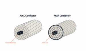
- Composite Core Conductors (ACCC and ACCR) replace the heavy steel core with a lighter, stronger composite material. ACCC uses a carbon fiber core, while ACCR uses an aluminum-matrix composite core.
- Annealed Conductors (ACSS) look like standard ACSR, but the outer aluminum strands are fully annealed (softened). This means the steel core carries all the mechanical tension, and since steel expands less than aluminum, the conductor sags much less.
- Alloy Conductors (TACSR) are another evolution of ACSR that use a special, heat-resistant aluminum alloy for the outer strands that maintains its strength at higher temperatures.
- GAP-Type Conductors (GTACSR) use a clever design that keeps the steel core but separates it from the outer aluminum strands with a small gap filled with heat-resistant grease, allowing the outer layers to expand and contract independently.
- INVAR Core Conductors (TACIR) use a core made of Invar, a special nickel-iron alloy with extremely low thermal expansion.
All of these technologies allow you to “re-conductor” existing transmission corridors. In some cases, to gain even more clearance, specialized crews can even “jack up” and extend the height of existing towers while the lines remain energized. These techniques are crucial for moving more power without the immense cost and difficulty of building entirely new lines.
The Hubs: The Transmission Substation
If transmission lines are the major arteries, then substations are the critical hubs that direct the flow of power. These complex facilities are the nodes where you transform voltages, connect different lines, and control and protect the grid. If you were to take a walk through a high-voltage substation, the first thing you would notice is the sheer scale of the equipment. Here are the key components and their roles:
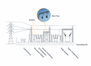
- Power Transformers are typically the largest pieces of equipment in the yard. As you learned in Part 1, they are the essential components that make high-voltage transport possible, stepping voltage up or down as needed.
- Circuit Breakers are your high-voltage switches. They are designed to interrupt the flow of power, either for planned maintenance or automatically in milliseconds during a fault. They are typically filled with an insulating medium like sulfur hexafluoride (SF6) gas or are built with a vacuum chamber to smother the arc.
- Disconnect Switches are used to physically and visually isolate a piece of equipment. They are a critical safety device for maintenance crews.
- Busbars are the rigid, heavy-duty conductors that serve as the main arteries within the substation, connecting all the different circuits and equipment.
- Instrument Transformers like Current Transformers (CTs) and Potential Transformers (PTs) allow you to safely connect measurement devices to high-voltage lines without making direct electrical contact. A CT uses the powerful magnetic field of the main line to induce a much smaller, proportional current.
- Capacitor Banks and Shunt Reactors are your tools for voltage control. Capacitor banks produce reactive power to boost voltage, while shunt reactors absorb it to lower voltage.
- Surge Arresters are the substation’s primary defense against lightning.
- The Grounding Grid is a critical but mostly invisible safety system buried below the surface. The Grounding Grid is a giant safety net that ensures any dangerous electricity is immediately and safely guided into the ground, keeping the area safe for anyone inside.
- Wave Traps are large coils that are part of a Power Line Carrier (PLC) communication system, which sends data over the transmission lines themselves.
- The control house is the control center of the substation, housing protective relays, control panels, meters, and communications equipment. It also contains banks of DC batteries to provide backup power.
All of this carefully engineered hardware stands ready to perform a dual mission. It must safely handle the immense power flowing through the station, while also managing the complex physical phenomena that only appear when you move high-voltage electricity over hundreds of miles.
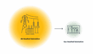
The Urban Solution: Gas-Insulated Substations
The sprawling outdoor substations you’re familiar with are known as Air-Insulated Substations (AIS). But in a dense city, you use Gas-Insulated Substations (GIS). In a GIS, all the key components are enclosed within sealed, metal tubes filled with sulfur hexafluoride (SF6) gas. SF6 is a far better electrical insulator than air, which allows for a substation with a footprint that can be as little as 10% of a conventional AIS.
The Unique Physics of a Vast Network
Moving power hundreds of miles introduces unique electrical challenges:
- Inductance and Capacitance: On long lines, the powerful magnetic field creates significant inductance (L), which consumes reactive power and causes voltage to drop. At the same time, the long parallel wires act like a giant capacitor, creating capacitance (C) that produces reactive power, which can sometimes cause voltage to rise (the Ferranti Effect).
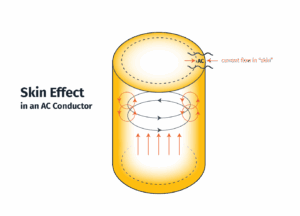
- Skin Effect: For AC power, current tends to flow on the outer surface or “skin” of a conductor, which increases its AC resistance and boosts power losses.
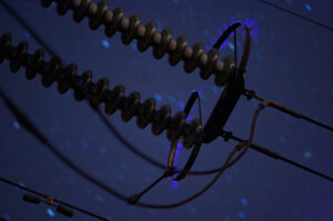
- Corona Discharge: The high voltage can rip electrons from the surrounding air, visible as a faint violet glow and audible as a buzzing sound. This is a direct power loss that also produces ozone and can create radio interference.
- Electromagnetic Induction: The powerful magnetic fields can create a “phantom” voltage on objects like pipelines or fences that share a corridor with a transmission line.
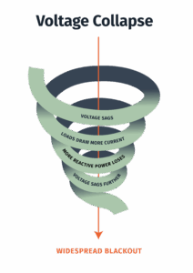
The Ultimate Risk: Voltage Collapse
Voltage stability is your grid’s ability to maintain a steady voltage after a disturbance. A voltage collapse begins when the grid can no longer supply the reactive power needed to support the voltage. This can trigger a dangerous downward spiral: voltage sags, some loads draw more current, which causes more reactive power losses, which causes the voltage to sag further. If not corrected, this cascade can lead to a widespread blackout.
Controlling Power Flow with Smart Valves
To get more precise, real-time control over power flow, you have Flexible AC Transmission Systems (FACTS), a family of power-electronic devices that act like smart valves.
- A Static VAR Compensator (SVC) is your classic tool for voltage support, using high-speed switches called thyristors to rapidly connect or disconnect capacitor and reactor banks.
- A Static Synchronous Compensator (STATCOM) is the next generation, using a voltage-source inverter to provide a smooth, continuous, and fast-acting source of reactive power.
- A Thyristor-Controlled Series Capacitor (TCSC) is installed in series with the line to dynamically change its overall impedance, encouraging or discouraging power to flow down that path.
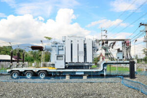
Mobile Equipment: Substations on Wheels
A mobile substation is a substation’s key components mounted on a semi-trailer. Their primary significance is for restoration. When a permanent substation is severely damaged, a mobile unit can be trucked in and energized in a matter of days instead of the months or years it can take to rebuild. They also provide flexibility for fast-changing loads, making them a key tool for grid resilience. Mobile substations represent a clever solution for resilience using established AC technology. But to solve even bigger challenges, like moving massive amounts of power over vast distances or underwater, you have to turn to a different kind of technology altogether.
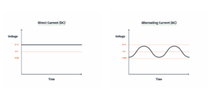
High-Voltage Direct Current (HVDC)
Interestingly, Direct Current (DC) is now used for specialized, high-power applications. For long-distance underground or underwater cables, the high capacitance leads to massive reactive power losses for AC. High-Voltage Direct Current (HVDC) solves this problem. Since DC doesn’t have the continuous charging and discharging of reactive power, it can move huge amounts of power efficiently through these cables, making it the go-to technology for connecting offshore wind farms or linking power systems across large bodies of water. This technology also gives you precise control over how much power flows down the line, but technologies like HVDC don’t solve the single biggest hurdle you will face in your career.
The Next Great Challenge: Expanding the Grid
For all its technical marvels, the transmission system faces a significant challenge that has less to do with physics and more to do with policy, economics, and public will. The grid you’re managing was largely built out in the mid-20th century. Now, for the first time in decades, you are facing significant load growth from the electrification of transportation and heating, plus the explosive demand from new data centers. At the same time, the transition to clean energy requires building thousands of miles of new high-voltage lines to connect remote wind and solar resources to the cities where the power is needed.
These factors have converged to create a significant challenge. Building new transmission is a key bottleneck in the energy transition, but it’s a process that involves many challenges. Securing the “right-of-way” for a new line can take over a decade, as it requires navigating a complex web of local, state, and federal permits and often faces strong “NIMBY” (Not In My Backyard) opposition. Furthermore, figuring out how to fairly allocate the multi-billion-dollar cost of a new line that crosses multiple states is a major source of conflict. Solving this transmission puzzle will be one of the most urgent factors of your career.
Conclusion
That’s the end of this module. You’ve now toured the vast circulatory system you’re responsible for. You understand the physical hardware, the unique physics at play, and the sophisticated technologies you can use to manage them. For all its resilience, this system faces the immense challenge of expansion in a world with growing electrical demand. It is a true marvel of engineering, and it’s now your job to keep it running.
In your next training, we’ll follow the power as it leaves your high-voltage transmission system and enters the distribution network.
Read the other posts in The Fantastic Machine series →
Loved the article? Hated it? Didn’t even read it?
We’d love to hear from you.